
Introduction
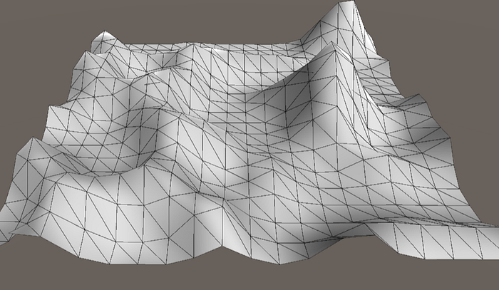
Welcome back to my second blog post! We shall continue our journey deeper into the world of Procedural Generation. In this blog, we’ll be creating our own procedural terrain mesh in Unity! My end goal is to teach everyone how to generate a terrain mesh like the image shown above.
Before we start programming, I’ll first go over everything we need to know about creating a terrain mesh. The topics I’ll be covering today are: geometry, mesh generation basics, noise, height maps, and I’ll conclude with a summary.
As ever, sit back and enjoy the adventure!
Geometry
In order to procedurally generate a mesh, its important that we familiarize ourselves with some basic geometric concepts as described below.

Square Quadrilateral (Quad)

For creating our terrain mesh, we’ll be using square quadrilaterals (quads). A square quad is a 2D shape that consists of 4 vertices, 4 edges, and 1 face, as shown above.
Mesh Generation Basics
Computer Graphics and Triangles


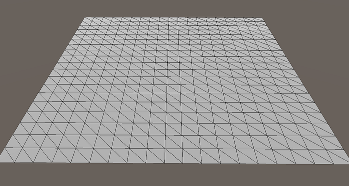
Within computer graphics, all shapes are comprised of triangles. There are a few reasons for this, but primarily its due to triangles being very efficient in terms of memory and they can be rendered extremely fast. As shown above, my terrain mesh is made up of several square quads and each of these quads are comprised of exactly two triangles.

Each triangle contains 3 vertices. In Unity, we can create a triangle by declaring an int array where each element of this array will correspond to a vertex point.
int[] triangles = new int[]
{
  0,1,2 //corresponds the vertex points at 0, 1, and 2
};
In Unity and many other engines, the elements in this int array must correspond to the vertices in a clockwise order which refers to Back-Face Culling.
Back-Face Culling
Within computer graphics, a method called Back-Face Culling is used to increase efficiency by only making front-facing triangles visible.
A triangle is considered to be front-facing if it corresponds to the vertices in a clockwise order. Whereas, if the triangles corresponds to the vertices in a counter-clockwise order, the triangle will either not be visible, or drawn incorrectly on the screen.
I’ve provided examples below for a better visualization of using incorrect triangle indices vs. correct triangle indices for generating a quad.


Generating a square quad

As I mentioned earlier, each square quad consists of two triangles, each mapping to three vertex points. The bottom left triangle (shaded in green) maps to 0, 1, and 2 vertex points. The top right triangle (shaded in blue) maps to 2, 1, and 3 vertex points. Both of these triangles are sharing the vertices at point 1 and 2.
Below is a code snippet to generate the above quad.

Vertex Attributes
Mostly all of the data in our mesh comes directly from the vertex attributes. Each vertex contains multiple attributes but the ones we’re mostly concerned with are the position, color, and normal attributes.
Position: The position of the vertex.
Color: The color of the vertex.
Normals: Determines the vertex direction and allows it to be shaded correctly.
Shared Vertices vs. Unshared Vertices
Both shared vertices and unshared vertices serve their own purpose. Each of these cases will affect how the mesh is shaded and ties in with the vertex normals.
Unshared vertices will result in crisp edges between the triangles. This is useful in sharp-edged objects like a cube. In order for vertices to be unshared, the edge vertices need to be doubled so that each triangle has it’s own set of unique vertices.
Shared vertices cause interpolation of the vertex normals, resulting in smooth edges between the triangles. This is useful for creating a curved surface such as our terrain mesh. To use shared vertices, we simply reuse the edge vertices so that each triangle will share some of it’s vertices with another triangle.
When learning about shared vertices and unshared vertices, I found it very confusing, so I’ve provided visual examples below to help you understand this concept better.


Mesh Components
In order to store data and render our mesh within Unity, we must attach both a Mesh Filter and a Mesh Renderer to our game object. Without having these two components, we won’t be able to generate our mesh.
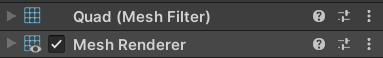
Mesh Filter: Stores data for the mesh.
Mesh Renderer: Uses data from the Mesh filter to render the mesh on screen.
Generating a terrain mesh
Alright, so now that we know the basics of mesh generation, we can start generating our terrain mesh.
In order to generate our mesh, we’ll be creating a grid of quads. From here, we’ll manipulate the height of the vertices which will make our mesh look like a terrain.
For manipulating our vertex height values, we’ll create a noise algorithm which we’ll interpret as our height map.
Noise
Okay, I know what you may be thinking. What does noise have to do with generating terrains and all that stuff? Well it turns out that noise can actually be very useful in generative algorithms!
Random Noise
This type of noise has random values that have no relationship with one another and is not very useful in terms of procedural generation.

Perlin Noise
While working on the original TRON movie in the early 1980s, a professor named Ken Perlin developed a noise function to make the Computer Generated Imagery (CGI) appear more realistic. This algorithm is called Perlin noise and it generates pseudo-random values that have a relationship to each other. The result of Perlin noise has a more organic appearance as opposed to that of random noise where the values have no relationship.

Perlin Noise in Unity
There is a built-in implementation of Perlin noise in Unity, and we’ll be using it to generate our terrain mesh.

Perlin noise requires two parameters for the X and Y coordinates and will return a fraction value between 0 and 1. In this case, I’ve provided the Z coordinate instead of the Y coordinate because we’re dealing with the X and Z axes for our terrain mesh.
An important thing to know is that Perlin noise will always return the same value for any integer value passed in as the coordinates. To avoid this, we must first convert the X and Z axes into floating point numbers before passing them into the Perlin noise function.
Perlin Noise Input Values
To further modify our noise algorithm, we can pass in values. I’ve listed the typical input values below that are used with Perlin noise.
Scale: Controls the zoom level of the noise. Decreasing the scale will make the noise zoom out. Whereas, increasing the scale will make the noise zoom in.
Octaves: Refers to the use of multiple levels of noise. The 1st octave is the base layer and will provide the overall noise shape. Each subsequent octave will make the noise increase in detail.
Lacunarity: Controls the frequency for every octave of noise which contributes to the amount of detail added for each octave.
Persistence: Controls the amplitude for every octave of noise which determines the impact each octave has on the overall shape.
Seed: A pseudo-random value used to offset the noise value so that appears different each time its generated. If we do not change the seed value, the generated noise will be the exact same, and this can be useful for debugging purposes.
Noise Comparison
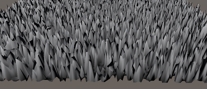
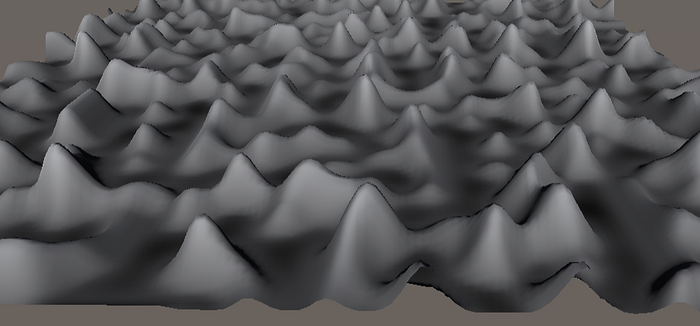
Random noise is very random and each value generated has absolutely no correlation to the previous or next value being generated. In terms of creating terrain, we use Perlin noise because the different values relate to each other giving the terrain a more organic and natural look.
I’ve provided two screenshots below for a better comparison between terrain that was generated using random noise (1st picture) and terrain that was generated using Perlin noise (2nd picture).
Height Maps

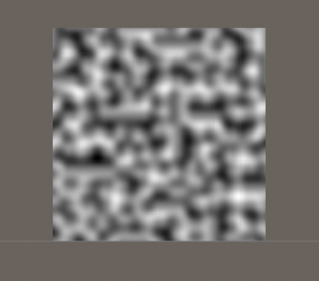
A height map is a 2D array of values, typically a greyscale image, where each pixel contains height data. The white areas represent high elevation, whereas the black areas represent low elevation. The grey areas represent base or neutral elevation. For our terrain mesh, we can directly interpret our noise algorithm as our height map.
Blog Summary
Alright so I know I’ve talked about a lot of different things in this blog post, but I’ll give a summary as to what we actually need to do for generating our terrain mesh.
Prep Step
To begin, we need to decide whether the map dimensions will be measured in quads or vertices.
Step 1
Next, we start by creating a 2D grid of vertices on the X and Z axes.
Step 2
After creating our vertices, we want to create our quads. In doing so, we need to create triangles that connect our vertices from step 1.
Step 3
At this point if we did everything correctly, we should have a flat grid of quads. We now want to start working on our noise algorithm.
Step 4
Using several input values, we can create our noise algorithm and give it a desired outcome.
Step 5
Now that we’ve created our noise algorithm, we can directly interpret it as our height map and apply it to the height value of our vertices.
Step 6
Next we can create a height multiplier value to further control the height of our vertices. At this point our mesh should now look like a mountainous terrain.
Step 7
Lastly, we want to give our terrain mesh some color. For this, we create an array of colors where each color corresponds to each vertex in the mesh.
Fine-Tuning
Alright well we now have a base for our terrain mesh. From here we can fine-tune our mesh by modifying the variables for a more desired outcome.
Demo Video
I’ve provided a video of me creating a procedural terrain mesh in Unity. If you have Unity installed on your PC, feel free to follow along!
If you would like to take a look at my scripts from this video, I’ve created a GitHub repository for them: https://github.com/kp4ws/ProceduralTerrain
Conclusion
At last all good things must come to an end. I hope you enjoyed the adventure of my two-part blog series within Procedural Generation. In my first blog, I taught you a broad overview of PCG and how it can be used in game development. In this second blog, I went more in depth and taught you how to procedurally generate a terrain mesh.
Using creativity, you can expand on what I’ve taught you and think of different ways you can implement Procedural Generation in your game development journey.
Have a wonderful day!
References
https://youtube.com/playlist?list=PLFt_AvWsXl0eBW2EiBtl_sxmDtSgZBxB3
https://catlikecoding.com/unity/tutorials/noise-derivatives/
https://gamedevacademy.org/complete-guide-to-procedural-level-generation-in-unity-part-1/
https://docs.unity3d.com/ScriptReference/Mathf.PerlinNoise.html
https://www.redblobgames.com/articles/noise/introduction.html
https://www.youtube.com/watch?v=ucuOVL7c5Hw&list=PL5KbKbJ6Gf9-d303Lk8TGKCW-t5JsBdtB
https://www.redblobgames.com/maps/terrain-from-noise/
https://www.youtube.com/watch?v=64NblGkAabk
https://en.wikipedia.org/wiki/Back-face_culling
https://www.scratchapixel.com/lessons/procedural-generation-virtual-worlds/perlin-noise-part-2
https://docs.unity3d.com/Manual/AnatomyofaMesh.html
https://en.wikipedia.org/wiki/Ken_Perlin
